
|
 |

Tested at the Frequency
...or "Why Not Test Ethernet Cables at the Frequency of The Signal?"
A while ago, in the course of a discussion about Ethernet cabling, we encountered an interesting objection to the way the Ethernet cabling spec is written. The spec requires that cables be tested across a broad frequency spectrum -- for Cat 5e, up to 100 MHz; for Cat 6, up to 250 MHz; and for Cat 6a, up to 500 MHz. The cable can fail by exceeding return loss or crosstalk targets at any frequency within the testing spectrum.
In response to that, one fellow suggested that testing across this broad spectrum was wholly unnecessary. Why not, he said, test the cable at the frequency of the signal running through it? Surely that frequency is the one that must be faithfully transmitted, and performance at other frequencies doesn't matter.
Not a bad question -- but it reflects a bit of a misunderstanding as to how digital signals look, and consequently contains a bad assumption as to what the "frequency" of the data stream actually is. Let's venture first into a familiar zone: radio and TV signals. In that domain we can see how this question seems to make sense, and then by contrast we can examine how very different the world of digital signalling is and why the question, as applied to Ethernet, makes less sense than it might at first seem.
Radio and TV: Bandwidth, and Frequency
We are all familiar with the concept, in radio and TV, of specific "channels." We expect, when the AM dial is at 1590, not to receive the signal from a station that's at 1000, just as we expect a TV tuned to Channel 4 not to also get Channel 5 at the same time. But what are these channels?
Well, consider the simple case of AM radio. The information an AM radio signal has to carry is pretty small -- an audio signal, with a top frequency of a few kilohertz. To carry this information, the audio signal is "modulated" onto a radio signal of a given frequency, say, 1000 kHz (1 MHz). Now, AM stands for "amplitude modulation," and the concept is that the strength of a 1000 kHz signal, in this case, is "modulated" by varying its amplitude in accordance with the sound wave that we want the station to carry. In fact, what happens when we do this is that the signal spreads out over a wider band of frequencies. Let's say we put a 4 kHz pure sinusoidal wave into the audio input of our transmitter; if we do that, and then look at the spectrum of the AM transmitter's output, we're going to see not just the 1000 kHz signal, but two "sideband" signals which appear at 996 kHz (the carrier frequency minus the tone frequency) and 1004 kHz (the carrier frequency plus the tone frequency).
This spread between the high and the low frequencies in our signal is its "bandwidth," and the bandwidth is a way to think about the "information" content of the signal. The carrier wave at 1000 kHz tells us nothing; all of the information, whether it's a 4kHz tone or a human voice, is in those sidebands (in fact, all of it can be found in one sideband alone, but in AM radio we use both) and the more information we need to modulate onto the signal, the more bandwidth we need. In the case of AM radio, since stations sit as little as 10 kHz apart, we can only use 10 kHz of bandwidth for them, limiting us to audio at 5 kHz and below.
If we have more information, we need more bandwidth to carry it. If we wanted AM stations to carry higher-frequency audio, we'd have to separate them further on the dial -- there is a direct relationship between the amount of information the signal contains and the amount of the frequency spectrum required to carry it. So, for example, while an AM radio signal sits in a little 10 kHz slot on the radio dial, a television channel has six hundred times as much spectrum space -- 6 MHz -- to carry its content (as well as having some more complex ways of modulating that content onto the signal).
Now, the original question asked above (why not tune your test to the frequency in use?) makes a great deal of sense in this context. Let's say we want a radio and an antenna to receive only one station: the AM station at 1000 kHz. Clearly, we do not care whether the antenna or the feedline or the radio is any good at 500 kHz, or at 1500 kHz. We are only interested in the performance from 995 to 1005 kHz, because we know the sidebands of a 1000 kHz AM station must all lie in that region. Indeed, poor performance for the antenna and receiver outside of that band is a GOOD thing -- because any signal that lies out there is not part of the signal we're trying to get. Because receivers are selective, we can have many, many radio stations all filling the air with signal at once, and we can zero in on the one we want.
Data versus Radio
A data network is run on a rather different principle. There are no other "stations" for our signal to compete with in a wired network, and that means that we don't need to modulate our data onto a radio carrier wave so as to put it on a different "channel" from another data stream. Think of it, instead, as "modulated DC." But what we DO have is a signal that needs to carry a vast amount of information -- much more than an AM radio audio program. Remember those sidebands? We needed 10 kHz of bandwidth to carry that AM signal, and we're going to need a heck of a lot of bandwidth if we are carrying, say, 10GBaseT because there's a lot of information to encode.
A digital signal does look a lot like a radio signal in some ways. It consists of a series of changes in voltage occurring over time, like a radio wave. But where a modulated RF signal is a relatively narrow-band phenomenon centered tightly around a carrier frequency, a data stream is a very different, wide-band phenomenon. In fact, it's completely inaccurate to suggest that a data stream has "a" frequency. If we take it and look at it in a spectrum analyzer, we see instead a signal that covers many frequencies over a wide range. To understand why this is, we need to understand a few things about these signals:
(1) Digital waves are square-ish: The ideal digital signal is a square wave -- instantaneous transitions in voltage between different discrete voltage levels. But square waves are problematic -- impossible to actually generate, and if we come close enough to generating them it can cause noise problems. The transitions, though not quite "square," are still sharp and sudden. Such a wave contains not only the primary frequency (for a 10101010... signal, 1/2 the bitrate) but also its odd harmonics -- so even a simple up-down at 100 MHz, say, has a large harmonic component at 300 MHz, and if we can't convey that harmonic faithfully we will lose a lot of the sharpness of the transitions -- very important to the receiving circuit.
(2) Digital waves are not perfectly periodic: If a digital signal contained the same sequence again and again, as in our simplified 10101010... example, it could convey no information. Encoding information into it inherently causes it to be unpredictable and this means that its "frequency" is not as easy to characterize. A sequence that goes 10101010 is oscillating at the bitrate (with the fundamental frequency, since one Hertzian wave is an up and a down, being 1/2 that bitrate), while a sequence that goes 110011001100 is oscillating at 1/2 the bitrate (but with the transitions just as sharp, so that now not only the 3rd harmonic, but also the 5th harmonic, becomes important to keeping those rising and falling slopes high). And a signal that's random-looking in sequence, of course, has a frequency profile which is all over the place.
(3) Multi-level encoding -- the signals are not just ones and zeros, but are multiple voltage values within a range -- means that what's going on is actually still more complex than that.
The result is that a data stream does not have "a" frequency around which it centers, but instead occupies a considerable band of frequencies. Let's take 100-BASE-TX as an example. We run it on Cat 5e cable, and the cable is tested all the way from 1 to 100 MHz. If we hook up a spectrum analyzer to the data stream, what does it look like? Here, courtesy of Paul Kish at Belden, is a chart showing the signal spectral density of a 100BASE-TX signal:
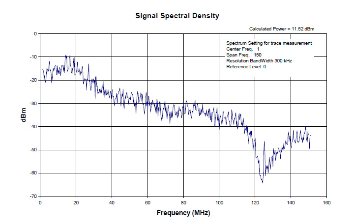
As you can see, far from having "a" frequency, the signal occupies a very broad frequency range. Mr. Kish's graph ends at 150 MHz, which is a full 50 MHz beyond the testing requirements for the cable, but as you can see, the high-frequency components of the signal still haven't petered out completely -- and those high frequencies are part of what's conveying the sharpness of transitions in the signal.
And so...
Should Ethernet cable be tested at the frequency at which it operates? Well, yes. But to get that statement to read correctly, for the expression "the frequency" we need to substitute "the frequencies." Because these signals are very wide-bandwidth phenomena, the testing criteria for them need to evaluate performance not just within a narrow range, but within a big chunk of spectrum. The applicable Ethernet cabling specs do, in fact, just this -- Cat 5e being tested to 100 MHz, Cat 6 to 250 MHz, and Cat 6a to 500 MHz.
How can you know that these criteria are met? There's really only one way, and that's to test every last cable assembly on a certification tester like our Fluke. Good cable and good connectors can be made into poor assemblies; and bad cable and bad connectors will not make good assemblies no matter what the skills of the assembler may be. The key is quality control throughout the process: quality cable manufacture, quality connector manufacture, quality assembly, and quality verification assured by testing each individual assembly.